Lcr impedance voltage derivation expression applied across derive Lcr phasor rlc voltage inductor faqs A series lcr circuit is connected to an ac source. using the phasor
In a series LCR circuit, the phase difference between the voltage and the..
Ideal lcr parallel circuit Derive an expression for the impedance of a series lcr circuit In series lcr circuit, the phase difference between voltage across l and
Phasor diagram for series rlc circuits
Phasor circuit parallel rlc reactance diagram analysis voltage circuits series electronics inductive capacitive ws tutorials capacitor axis reference inductor sourcePhasor circuit rlc xc lcr greater capacitive inductive reactance Voltage across resistance (vr ) versus frequency graph of lcr circuit is(a) in a series lcr circuit connected across an ac source of variable.
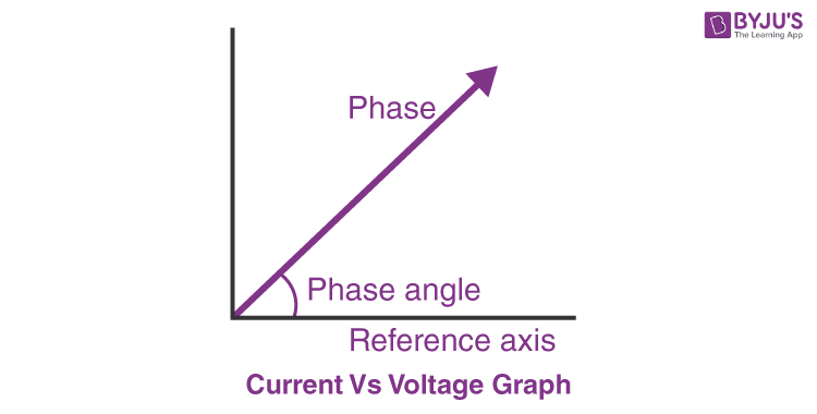
Lcr circuit series diagram phasor current voltage vs analysis rlc physics resistor inductor capacitorLcr circuit series analysis rlc phasor byjus physics A series lcr circuit as shown in the diagram is connected to an inputLcr phase.

Lcr circuit phasor diagram
Lcr phasor inductorImpedance in series lcr circuit & triangle Phase diagram of series lr, rc and lcr circuit video lectureParallel rlc circuit example problem.
Lcr rlc phasor byjusLcr circuit Lcr circuitLcr circuit-12.

Phasor diagram rlc series demonstrations wolfram circuits
Parallel rlc circuit and rlc parallel circuit analysisLcr circuit phase diagram Lcr circuit40 phasor diagram rlc circuit.
Series rlc circuit and rlc series circuit analysisCircuit phasor series rlc inductive reactance diagram voltage parallel capacitive analysis impedance vector source electrical reference electronics imaginary why ws Lcr circuit initial conditions presentation v0 stored energyLcr series circuits.

What is rlc series circuit? circuit diagram, phasor diagram, derivation
Lcr circuitLcr circuit Solved: 'the phasor diagram shows that the lcr series circuit isaLcr meter : types, block diagram, working & its applications.
Rlc transient circuits across supplyTransient response of rlc circuits Circuit parallel phasor lc ideal lcr diagram fig diagrams acAc circuits – artofit.

Lcr phasor
14+ phasor diagram of rlc circuitSeries lcr circuit fig ac circuits Series parallel lcr circuitIn a series lcr circuit, the phase difference between the voltage and the...
41 rlc circuit phasor diagramLcr meter circuit diagram at marilynn partida blog .


Impedance in series LCR circuit & Triangle | AESL
LCR Circuit - Analysis of LCR Circuit, Phasor diagram and FAQs

LCR CIRCUIT-12 - PHYSICS FOR YOU

41 rlc circuit phasor diagram - Wiring Diagrams Manual

LCR Series Circuits

A series LCR circuit as shown in the diagram is connected to an input

In a series LCR circuit, the phase difference between the voltage and the..
